63 Results
View results:
Sort by:

For the ultimate limit state design, EN 1998‑1, Sections 2.2.2 and 4.4.2.2 require a calculation considering the second‑order theory (P‑Δ effect). This effect may be neglected only if the interstory drift sensitivity coefficient θ is less than 0.1.

This example shows you how to quickly determine the buoyancy or the uplift limit state of a vessel in RFEM.

This article discusses the options available for determining the nominal flexural strength, Mnlb for the limit state of local buckling when designing according to the 2020 Aluminum Design Manual.

The Construction Stages Analysis (CSA) add-on allows for the design of member, surface, and solid structures in RFEM 6 considering the specific construction stages associated with the construction process. This is important since buildings are not constructed all at once, but by gradually combining individual structural parts. The single steps in which structural elements, as well as loads, are added to the building are called construction stages, whereas the process itself is called a construction process.
Thus, the final state of the structure is available upon completion of the construction process; that is, all the construction stages. For some structures, the influence of the construction process (that is, all the individual construction stages) might be significant and it should be considered so that errors in the calculation are avoided. A general overview of the CSA add-on is given in the Knowledge Base article titled “Consideration of Construction Stages in RFEM 6”.

RFEM 6 offers the Aluminum Design add-on to design aluminum members for the ultimate and serviceability limit states according to Eurocode 9. In addition to this, you can perform design according to ADM 2020 (US Standard).

In accordance with Sect. 6.6.3.1.1 and Clause 10.14.1.2 of ACI 318-19 and CSA A23.3-19, respectively, RFEM effectively takes into consideration concrete member and surface stiffness reduction for various element types. Available selection types include cracked and uncracked walls, flat plates and slabs, beams, and columns. The multiplier factors available within the program are taken directly from Table 6.6.3.1.1(a) and Table 10.14.1.2.

The calculation of complex structures by means of finite element analysis software is generally performed on the entire model. However, the construction of such structures is a process carried out in multiple stages where the final state of the building is achieved by combining the separate structural parts. To avoid errors in the calculation of overall models, the influence of the construction process must be considered. In RFEM 6, this is possible using the Construction Stages Analysis (CSA) add-on.

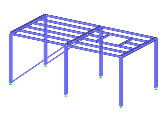
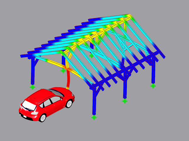
The RF-/LIMITS add-on module allows you to compare the ultimate limit state of members, member ends, nodes, nodal supports, and surfaces (RFEM only) by means of a defined ultimate load capacity. Furthermore, you can check nodal displacements and cross-section dimensions. In this example, the column bases of a carport are to be compared with the maximum allowable forces specified by the manufacturer.
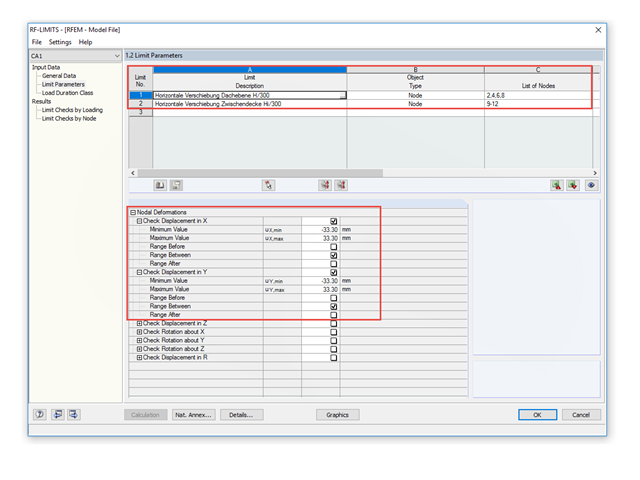
To control the lateral displacements of a model, you can use the RF-/LIMITS add‑on module. This add‑on module allows you to, for example, run a serviceability limit state analysis to find horizontal nodal deformations and to set it against a limit value.

With the orthotropic elastic-plastic material model, you can calculate solids with plastic material properties in RFEM 5 and evaluate them according to the Tsai‑Wu failure criterion. The Tsai-Wu criterion is named for Stephen W. Tsai and Edward M. Wu, who published it in 1971 for plane stress states.

Shrinkage and creep are time-dependent deformation properties of concrete that usually have to be considered in the serviceability limit state design.

The classification of cross-sections according to EN 1993-1-1 using Table 5.2 is a simple method for designing the local buckling of cross-section parts. For cross-sections of cross-section class 4, it is then necessary to determine the effective cross-section properties according to EN 1993-1-5 in order to consider the influence of local buckling in the ultimate limit state designs.

When connecting tension-loaded components with bolted connections, the cross-section reduction due to the bolt holes must be taken into account in the ultimate limit state design. This article describes how the design of the tension resistance according to DIN EN 1993‑1‑1 can be performed with the net cross-section area of the tension member in the RF‑/STEEL EC3 add-on module.

In the RF‑/HSS add‑on module, you can analyze the connections for nodes at which hollow sections join. RF‑/HSS performs the ultimate limit state designs according to EN 1993‑1‑8:2005.

Table 3.1 of EN 1993‑1‑8:2010‑12 defines the nominal values of the yield strength and the ultimate limit strength of bolts. The bolt classes given here are 4.6, 4.8, 5.6, 5.8, 6.8, 8.8, 10.9. The note for this table states that the National Annex may exclude certain bolt classes. For the NA of Germany, these are the bolt classes 4.8, 5.8, and 6.8.

In Part 1, the selection of the design criteria for dimensioning the reinforcement for the serviceability limit state design in RF‑CONCRETE Members and CONCRETE was explained. Now, we go into detail for the function "Find economical reinforcement for crack width design".
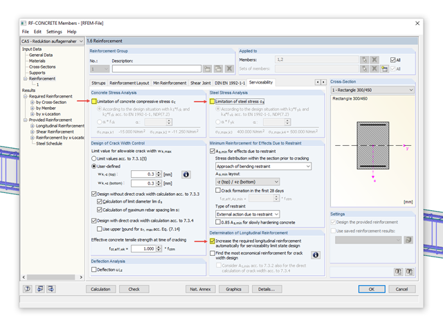
The RF-CONCRETE Members and CONCRETE add-on modules provide the option for "Dimensioning of Longitudinal Reinforcement for Serviceability Limit State". You can select the design criteria for the calculation of the longitudinal reinforcement.

This technical article deals with the design of structural components and cross-sections of a welded truss girder in the ultimate limit state. Furthermore, the deformation analysis in the serviceability limit state is described.
The steady state for periodically excited structures can be determined by means of the modal analysis in the DYNAM Pro - Forced Vibrations add-on module. This is an advantage if only the structure's steady state is of interest. Instead of a complete solution of the equation of motion, only a special solution is displayed.

The European standard EN 1993-1-8, Section 4.5.3.3. provides the user with a simplified method for the ultimate limit state design of fillet welds. According to the standard, the design is fulfilled if the design value of the resultant acting on the fillet weld area is smaller than the design value of the weld's load-bearing capacity. Thus, if you want to dimension the weld for a surface model, you will be faced with a variety of results due to the nature of FEM calculations. Therefore, we show in the following text how to determine the force components from the model.

Describing the procedure for the serviceability limit state design of a floor slab made of steel fiber reinforced concrete. This article shows how to perform the corresponding design for the SLS by means of the iteratively determined FEA results.

The design of cold-rolled steel products is defined in EN 1993-1-3. Typical cross-section shapes are channel, C, Z, top hat, and sigma sections. These are cold-rolled steel products made of thin-walled sheet metal that has been cold-formed by roll-forming or bending methods. When designing the ultimate limit states, it is also necessary to ensure that local transverse forces do not lead to compression, crippling of the web, or local buckling in the web of the sections. These effects can be caused by local transverse forces by the flange into the web, as well as by support forces at the supported points. Section 6.1.7 of EN 1993-1-3 specifies in detail how to determine the resistance of the web Rw,Rd under local transverse forces.

Utilize the RF-/STEEL Cold-Formed Sections module extension to perform ultimate limit state designs of cold-formed sections according to EN 1993-1-3 and EN 1993-1-5. In addition to the cold-formed cross-sections from the cross-section database, you can design general cross-sections from SHAPE-THIN.

Steel-fiber-reinforced concrete is mainly used nowadays for industrial floors or hall floors, foundation plates with low loads, basement walls, and basement floors. Since the publication in 2010 of the first guideline about steel-fiber-reinforced concrete by the German Committee for Reinforced Concrete (DAfStb), a structural engineer can use standards for the design of the steel fiber-reinforced concrete composite material, which makes the use of fiber-reinforced concrete increasingly popular in construction. This article describes the nonlinear calculation of a foundation plate made of steel fiber-reinforced concrete in the ultimate limit state with the FEA software RFEM.
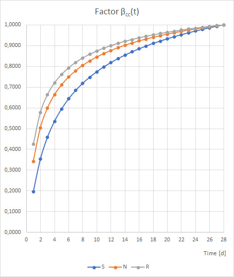
When determining the minimum reinforcement for the serviceability limit state according to 7.3.2, the applied effective tensile strength fct,eff has a significant influence on the determined amount of reinforcement. The following article gives an overview about determining the effective tensile strength fct,eff and the input options in RF-CONCRETE.
.png?mw=640&hash=1be9a846b1f57190540c7fc7f46f44cd40ab7029)
The calculation of structures based on digital twins is becoming an everyday task in the engineering office. If a digital building model already exists, you want to continue to use the information contained in it as seamlessly as possible. This states extensive requirements with regard to modeling and interfaces for BIM-compatible structural analysis software.

In accordance with Sec. 6.6.3.1.1 and Sec. 10.14.1.2 of ACI 318-14 and CSA A23.3-14, respectively, RFEM effectively takes into consideration concrete member and surface stiffness reduction for various element types. Available selection types include cracked and uncracked walls, flat plates and slabs, beams, and columns. The multiplier factors available within the program are taken directly from Table 6.6.3.1.1(a) and Table 10.14.1.2.

The fire resistance design can be performed according to EN 1993-1-2 in RF-/STEEL EC3. The design is carried out according to the simplified calculation method for the ultimate limit state. Claddings with different physical properties can be selected as fire protection measures. You can select the standard temperature-time curve, the external fire curve, and the hydrocarbon curve to determine the gas temperature.

When designing a steel cross-section according to Eurocode 3, it is important to assign the cross-section to one of the four cross-section classes. Classes 1 and 2 allow for a plastic design; classes 3 and 4 are only for elastic design. In addition to the resistance of the cross-section, the structural component's sufficient stability has to be analyzed.
The fundamental requirements of a structural system are (according to the basis of structural design) sufficient ultimate limit state, serviceability, and resistance. Structures must be designed in such a way that no damage occurs due to events such as the impact of a vehicle.